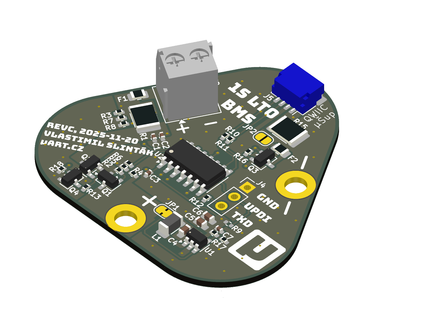
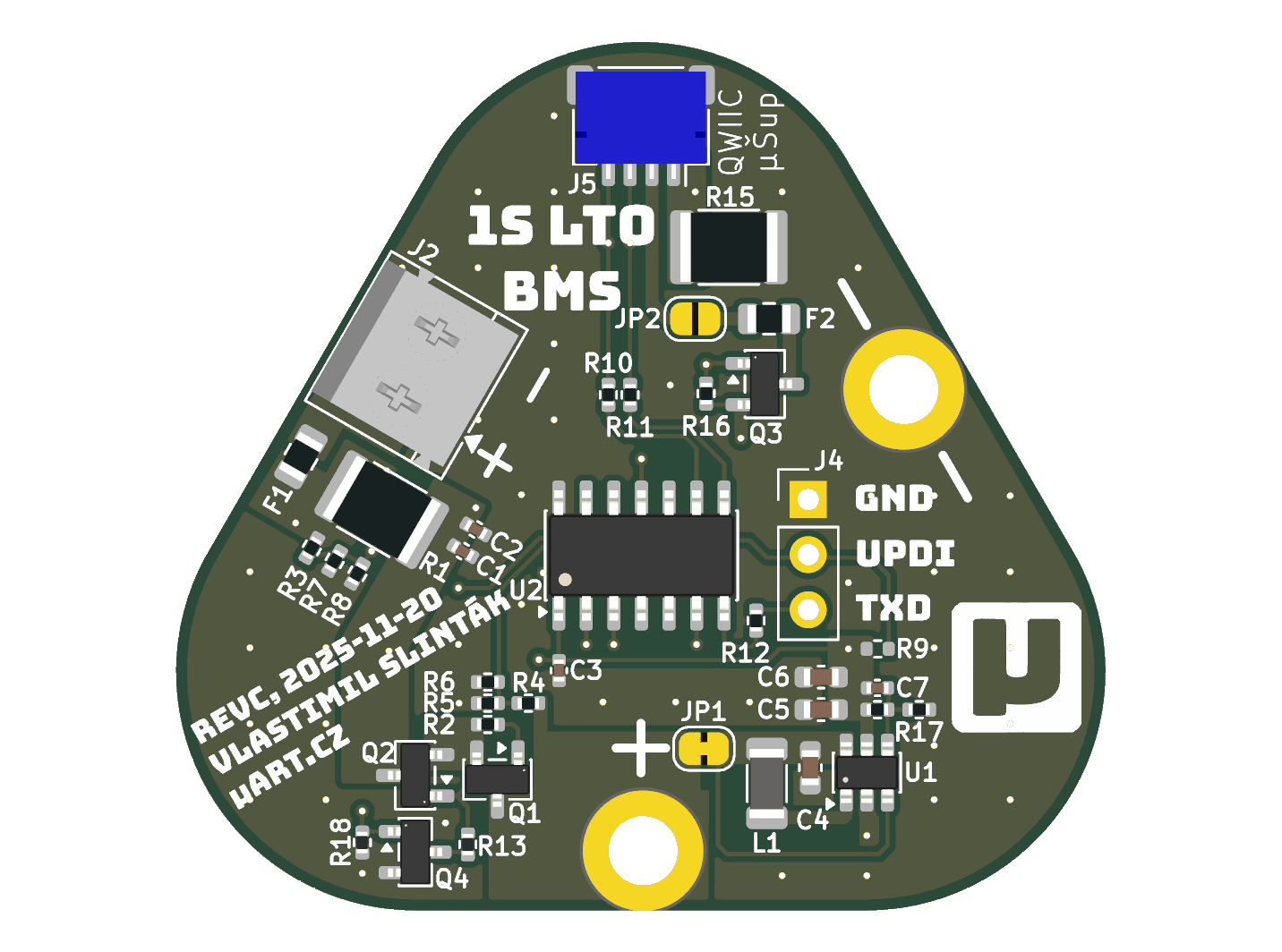
LTO Battery Management System (revision C)
BMS for single-cell (1S)
Lithium Titanium Oxide batteries
with over-current protection, under-voltage lockout (undervoltage
lockout), and over-voltage lockout (overvoltage lockout),
including capacity and current measurement.
Measured values such as instantaneous current, cell voltage, total cycle count,
SoC (state of charge), and more are available over the I2C bus on the
QWIIC/µŠup connector.
The maximum continuous discharge and charge current is 1 A; short-term (up to 10 s)
discharge and charge current is 2 A. The minimum cell voltage at which UVLO
triggers is 1.7 V by default, and 2.8 V for OVLO. These values can be changed via
I2C writes.
This BMS is designed primarily for battery-powered IoT sensors with lower current
requirements (up to 1 A), charged by a solar panel, and for outdoor temperatures
in Central Europe (-25 to 40 C).
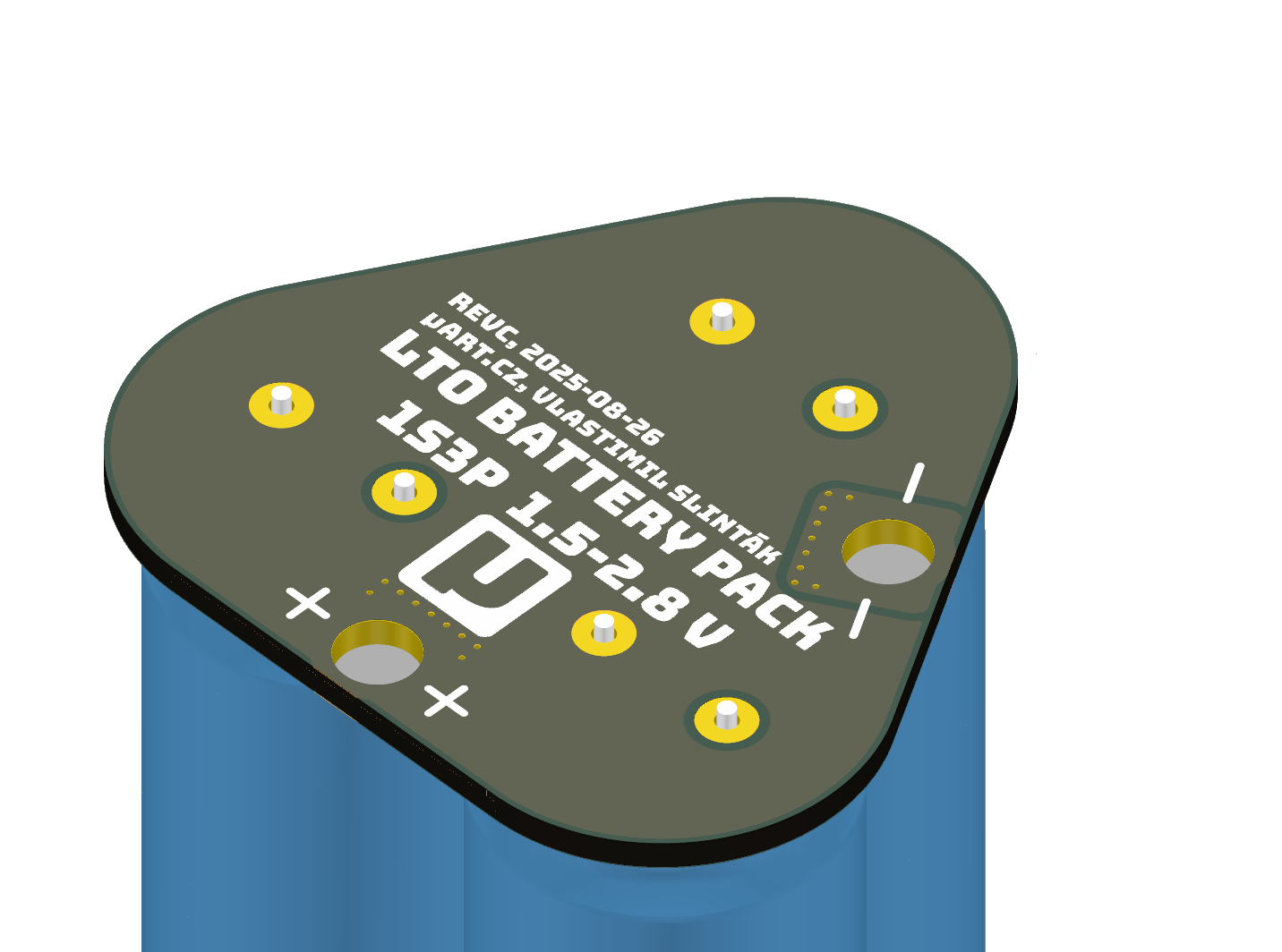
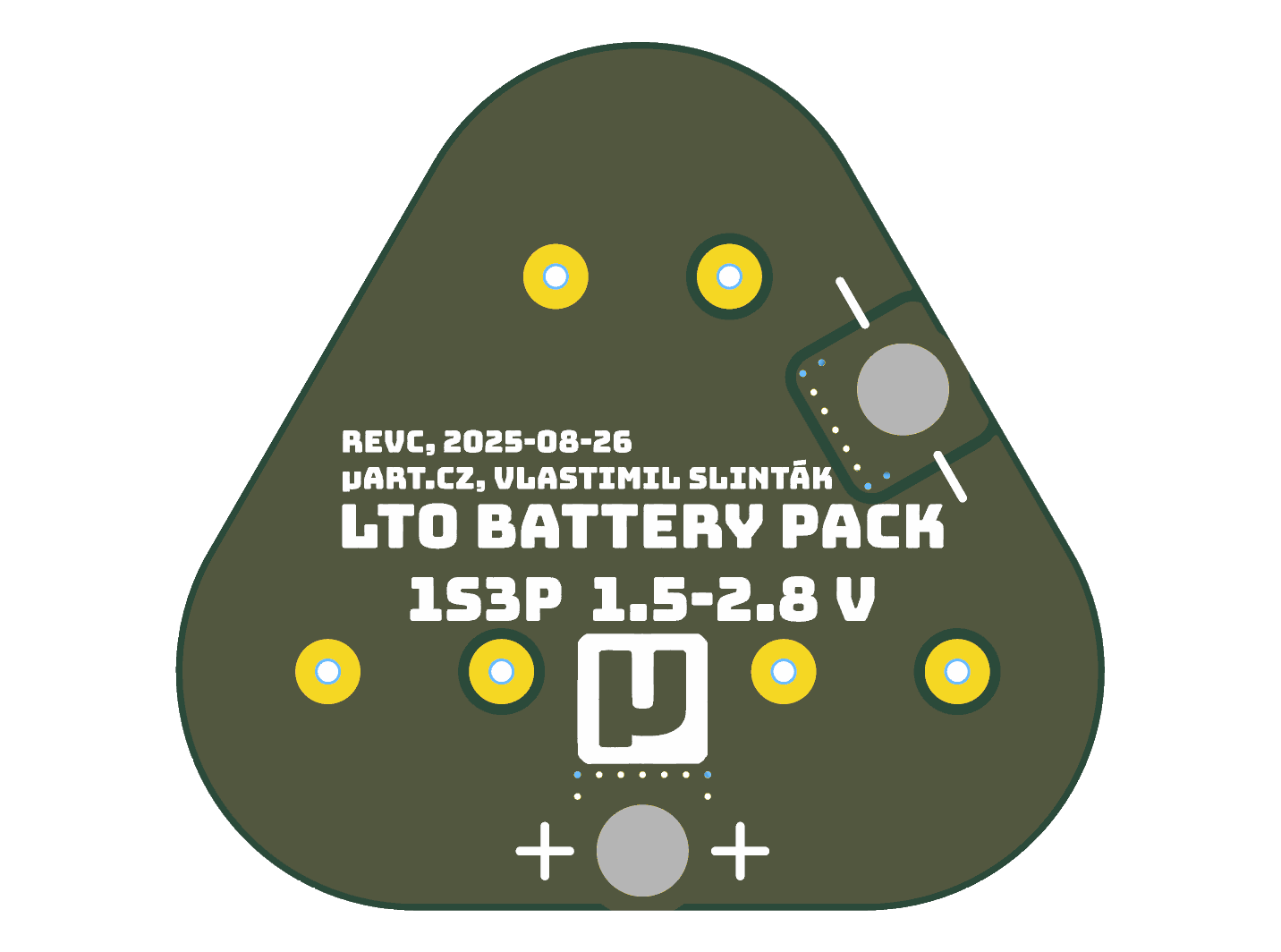
This BMS pairs with the LTO Battery Pack; both boards are designed to be joined
to form a single 1S3P LTO pack with electrical protection.
The product is also available on my Lectronz store:
https://lectronz.com/products/lto-battery-pack-with-bms.
Changes since revision B:
- Fixed the P-MOSFET switch wiring that failed to disconnect the battery when the input was 1.5 V higher than
VBATT.
cutoff signal logic is now inverted; the load disconnects when the signal is HIGH.3V3CUTOFF moved to PA5, away from the RXD pin on the ATTiny824.
Downloads: